26 Results
View results:
Sort by:

In RFEM 6 it is possible to define multilayer surface structures with the help of the “Multilayer Surfaces” add-on. Hence, if you have activated the add-on in the model’s Base Data, it is possible to define layer structures of any material model. You can also combine material models of, for example, isotropic and orthotropic materials.

The quality of the structural analysis of buildings is significantly improved when the soil conditions are considered as realistically as possible. In RFEM 6, you can realistically determine the soil body to be analyzed with the help of the Geotechnical Analysis add-on. This add-on can be activated in the model’s Base Data as shown in Image 01.

RFEM 6 includes the Form-Finding add-on to determine the equilibrium shapes of surface models subjected to tension and members subjected to axial forces. Activate this add-on in the model's Base Data and use it to find the geometric position in which the prestress of lightweight structures is in equilibrium with the existing boundary conditions.

Building Model is one of the special solution add-ons in RFEM 6. It is an advantageous tool for modeling, with which building stories can be created and manipulated easily. Building Model can be activated at the beginning of the modeling process and afterwards.
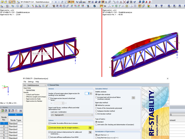
When analyzing structural elements susceptible to buckling by using the modules RF‑STABILITY (for RFEM) or RSBUCK (for RSTAB), it might be necessary to activate the internal division of members.

The RF‑/STEEL EC3 add-on module can perform the design of fillet welds for all parametric, welded cross-sections of the cross-section library. For this, the option must be activated in the detail settings of the module. As an alternative, you can also use a surface model for the design.

In RFEM, surfaces are automatically connected if they have common boundary lines. If the definition line of a surface is lying in another surface, the line is automatically integrated into the surface, provided that it is a planar surface. For quadrangle surfaces, however, automatic object detection would be relatively time-consuming. For this reason, the corresponding function is deactivated. The integrated objects must be specified manually.
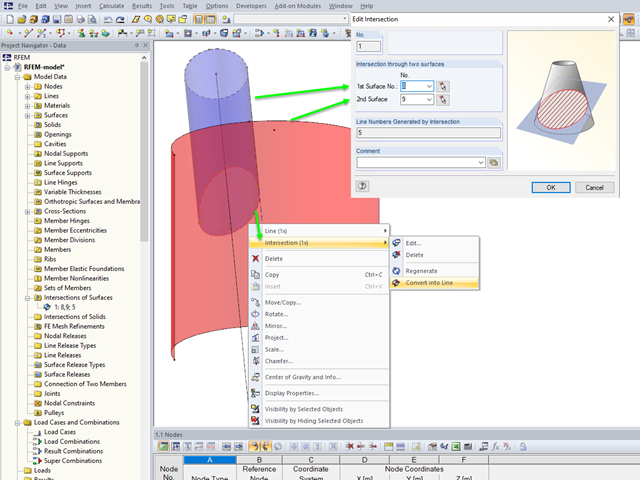
If you want to model two intersecting surfaces, RFEM offers you the possibility to create the section line automatically. In the program, this function is referred to as intersection. When generating an intersection, the modeled surface is split into components. This has the advantage that the components can be taken into account in the determination of the internal forces, or deactivated.

If nonlinear effects - such as failing supports, foundations, member nonlinearities, or contact solids - are used in the model, you can deactivate them in the global calculation parameters.

In addition to the basic combination rules of EN 1990, there are other combination conditions for actions on road bridges specified in EN 1991‑2 that must be taken into account. RFEM and RSTAB provide automatic combinatorics that can be activated in the General Data when selecting the standard EN 1990 + EN 1991‑2. The partial safety factors and combination coefficients depending on the action category are preset when selecting the respective National Annex.
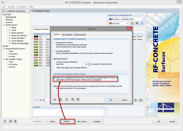
In order to use internal forces from average regions also for the design of concrete surfaces, you have to activate them in the module. For this, click the [Details] button in the "Tools" tab and select the option "Apply the averaged internal forces in the defined average region for the ULS calculation and for the analytic method of SLS calculation."
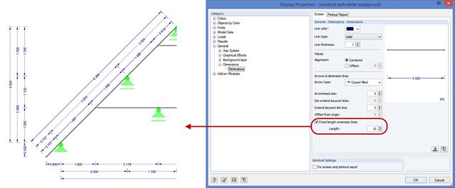
In RFEM and RSTAB, you can now define the guidelines of dimensions with a fixed length. This new option allows you to define dimensions without having the structure covered by the guidelines. This way, dimensioning is clearer. You can activate this option under "Display Properties" → "General" → "Dimensions".
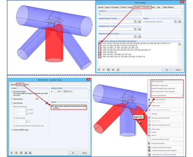
If intersections created in RFEM 4 are opened in an RFEM 5 file, the file management of intersections remains in the old format for compatibility reasons. Thus, the individual partial surfaces of the intersection can be activated or deactivated using only the "Integrated/Components" tab, all partial surfaces can only have the same thickness, and it is impossible to use the separate FE mesh refinement for the individual surface components.
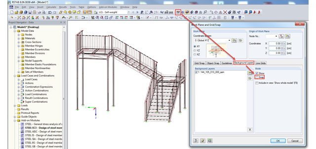
In RFEM and RSTAB, you can import background layers from a DXF file. If the main nodes of the model have already been set, it can be useful to deactivate the snap mode of the background layer.

The RF‑/STEEL Warping Torsion module extension of the RF‑/STEEL EC3 add‑on module allows you to design members with asymmetric cross‑sections. The new option is fully integrated in the design module and can be activated for sets of members.
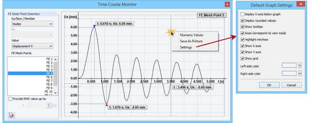
The Time Course Monitor displays the results of a time history analysis from RF‑/DYNAM Pro – Forced Vibrations. The graphic can be adjusted in the settings. This can be reached by right-clicking in the shortcut menu. For example, you can activate or deactivate the grid in the graphic. Those changes are overtaken into the printout report when you print the graphic.
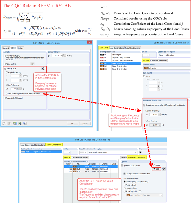
The CQC (Complete Quadratic Combination) rule has been available in RFEM and RSTAB since version X.06.3039. In the General Data of the model you can activate the CQC rule, and for Load Cases of the "Earthquake" type two new properties are available: "Angular frequency" and "Lehr's damping".

As in RFEM, load combinations can be generated automatically in RF‑PIPING. This feature is activated by default and creates the recommended load and result combinations for piping design. It is necessary to assign the relevant action category to load cases in order to generate the correct combinations. To do this, new action categories have been implemented specifically for loads on piping.
Pressure temperature conditions are generated as the sets of the first (second, third, and so on) load case of the "Pressure" category and the first (second, third, and so on) load case of the "Temperature" category. The default setting can be reviewed or adjusted in the "Grouping of Thermal and Internal Pressure Load Cases for Operating Combinations" dialog box. You can access this dialog box by clicking the corresponding button in the "Piping Load Combinations" tab of the "Load Cases and Combinations" dialog box. This dialog box is automatically offered to check your entries in the case of any change of the load case from the "Pressure" or "Temperature" category.
Pressure temperature conditions are generated as the sets of the first (second, third, and so on) load case of the "Pressure" category and the first (second, third, and so on) load case of the "Temperature" category. The default setting can be reviewed or adjusted in the "Grouping of Thermal and Internal Pressure Load Cases for Operating Combinations" dialog box. You can access this dialog box by clicking the corresponding button in the "Piping Load Combinations" tab of the "Load Cases and Combinations" dialog box. This dialog box is automatically offered to check your entries in the case of any change of the load case from the "Pressure" or "Temperature" category.
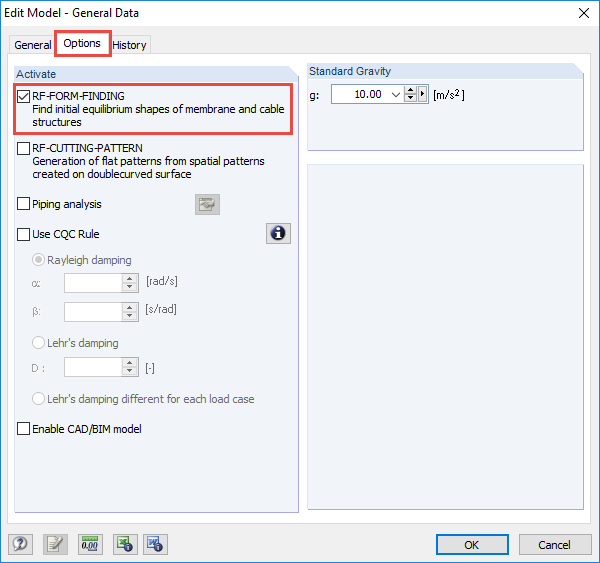
The RF-FORM-FINDING add-on module determines equilibrium shapes of membrane and cable elements in RFEM. In this calculation process, the program searches for such geometric position where the surface stress/prestress of membranes and cables is in equilibrium with natural and geometric boundary conditions. This process is called form-finding (hereinafter referred to as FF). The FF calculation can be activated in RFEM globally in the "General Data" of a model, "Options" tab. After selecting the corresponding option, a new load case or a calculation process called RF-FORM-FINDING is created in RFEM. An additional FF parameter is available for defining surface stress and prestress when entering cables and membranes. By activating the FF option, the program always starts the form-finding process before the pure structural calculation of internal forces, deformation, eigenvalues, etc., and generates a corresponding prestressed model for further analysis.
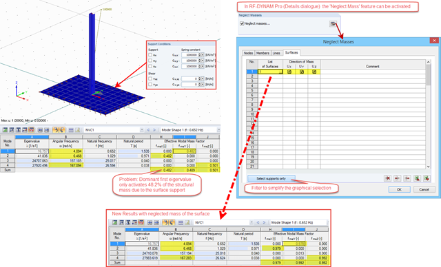
As of the version 5.06.1103, masses of nodes, lines, members, and surfaces can be neglected in RF‑DYNAM Pro. The setting to activate this feature can be found in the Details dialog box; the neglected masses are valid for all defined mass cases.
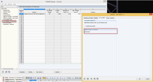
As of program version X.06.1103, you can perform serviceability limit state design checks of antennas in RF‑/TOWER Design. You can activate this function under [Details] → "Serviceability". Then, the limit values can be adjusted in Window 1.10.2, Serviceability of Antennas.
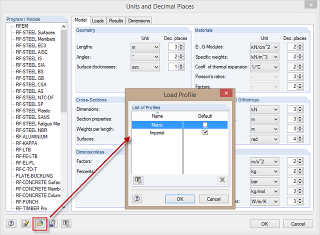
When changing the units from the metric to the imperial measurement system, it is not necessary to change all the units individually. To do this, corresponding unit profiles are available in the "Units and Decimal Places" dialog box, which you can activate as shown in the picture.
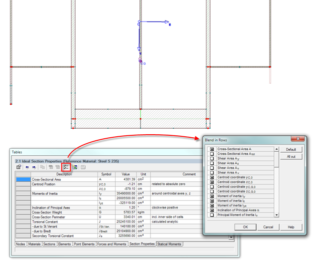
The result window of the cross-section properties can be adjusted individually using the [Filter] button in the table menu bar. You can then activate or deactivate the individual cross-section parameters in the dialog box.
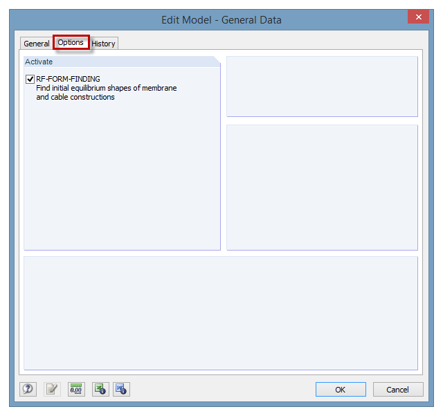
The RF‑FORM‑FINDING add‑on module can be activated in the "Edit Model - General Data" window, "Options" tab. By activating the module, a new RF‑FORM‑FINDING load case is created and an additional menu appears in the main program, allowing for the definition of prestress conditions for membrane and cable elements.
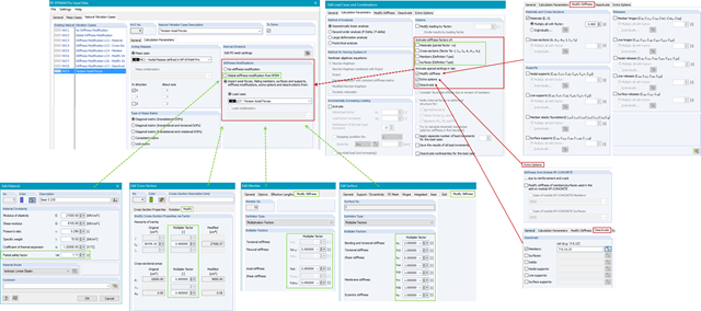
In RF-/DYNAM Pro - Natural Vibrations, you can import axial forces and stiffness modifications from any Load Case (LC) or Load Combination (CO). You can modify material, cross‑section, member, and surface properties and activate these modifications in the LC/CO calculation parameters.
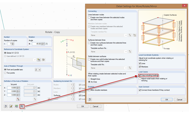
In order to also consider loading when copying, mirroring, or rotating, the corresponding option must be activated. To do this, select the corresponding check box in the "Detail Settings for Move/Rotate/Mirror" dialog box. Then, loading is included when copying until you deactivate this function.